Converting from Hex Microcode to Micro Assembly Language
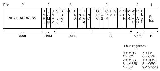
The above diagram illustrates the layout of the microinstruction for Mic-1.
Each bit represents a line to the data path.
It is inconvenient to use this representation when discussing the microcode,
so the book adopts a Micro Assembly Language (MAL). It is a straight forward
process to change the hex microcode into MAL.
Notice that the hex instruction has 6 areas
-
Next Address
-
JAM
-
ALU and Shifter
-
C Bus Registers
-
Memory
-
B Bus register
Each part corresponds to a section of a MAL instruction.
B Bus Register
The 4 bits for the B Bus Register are sent through a decoder so that one
of the nine input registers is gated onto the B Bus.
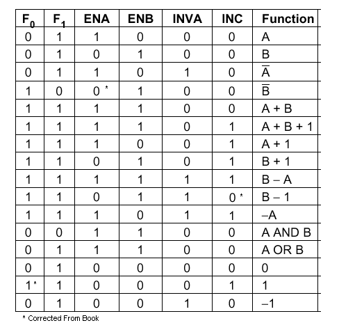
ALU and Shifter
The ALU operation is set from the above table. The shifter is capable of:
don't shift, shift right arithmetic 1, and shift left logical 8. The ALU
uses the A and B buses as input. In the data path, H is always wired to the
A Bus, and the register for the B Bus is specifed by the B Section of the
hex microinstruction. Whereas the ALU operation should be specified as A
+ B, we will always use H for A, and use the name of the register that is
sent to the B Bus, eg. H + OPC.
C Bus Registers
For each bit that is set in this section, the corresponding register is written
with the results of the ALU operation. For instance, if the OPC and PC bits
are set, then both will get the result of the operation.
OPC = PC = ALU operation
The calculation from the ALU and Shifter will commute to each of the registers
on the left of each equal sign.
Next Address and JAM
These fields are used to determine the next address.
-
JMPC
-
If JMPC is set, then the MAL instruction will have:
goto(MBR or
    NEXT_ADDRESS)
. Examples of instructions with JMPC set are
wide1 and Main1.
-
JAMN
-
If JAMN is set, then the MAL instruction will have:
if (N) goto
    true_label else goto false_label
Be aware that in the layout of the microcode, the address for
true_label is 256 greater than the address for false_label.
-
JAMZ
-
If JAMZ is set, then the MAL instruction will have:
if (Z) goto
    true_label else goto false_label
Be aware that in the layout of the microcode, the address for
true_label is 256 greater than the address for false_label.
-
None
-
If none of the JAM bits are set, then the MAL instruction will have:
goto
    (NEXT_ADDRESS)
Please note that for brevity, the microcode in the book omits this statement
from all of the MAL statements. On a homework or an exam, I will expect you
to include this statement in the MAL instruction.
Memory
These bits indicate when the corresponding operation will begin. It is possible
to perform a READ and a FETCH at the same time, as well as performing a WRITE
and a FETCH at the same time. It is not allowed to perform a READ and a WRITE
at the same time. This is done for simplicity: we are assuming that there
is always a hit in the code and data caches, and that both caches can be
accessed simultaneously.
Examples of changing MAL into hex, and hex into MAL
Consider a few instructions from the microcode for Mic-1
-
Main1: PC = PC + 1; fetch; goto (MBR)
-
The fields of the hex microinstruction can be filled in as follows
-
JMPC is set, since the MBR is referenced in the goto. JAM Field: 100
-
NEXT_ADDRESS is 0x000. Since this is a JMPC, and the format is goto (MBR
or NEXT_ADDRESS), then the NEXT_ADDRESS field must be 0.
-
Shifter is not used, so its two bits are 0.
-
ALU operation is B + 1: 110101
-
Only PC is being written. C Fields: 000000100
-
Code is being fetched. Memory Field: 001
-
PC is being gated onto the B Bus. B Field: 0001
Binary Format
000000000 100 00110101 000000100 001 0001
Hex Format
004350211
-
iflt1: MAR = SP = SP - 1;rd
-
The fields of the hex microinstruction can be filled in as follows
-
The JAM bits are all 0.
-
NEXT_ADDRESS is 0x023. There is actually a
goto(iflt2) implied. I will assume that iflt2 has
address 0x023.
-
Shifter is not used, so its two bits are 0.
-
ALU operation is B - 1: 110110
-
MAR and SP are being written. C Fields: 000001001
-
Data is being read. Memory Field: 010
-
SP is being gated onto the B Bus. B Field: 0100
Binary Format
000100011 000 00110110 000001001 010 0100
Hex Format
1183604A4
-
42A140008
-
-
binary format
010000101 010 00010100 000000000 000 1000
-
NEXT_ADDRESS is 0x085. Note that the high bit of the NEXT_ADDRESS field is
0. This is essential for the conditional branch to work. If the branch is
taken, then the address will be modified by placing a 1 in the high bit of
NEXT_ADDRESS. If the branch is not taken, then the address will not be modified.
If the high bit of NEXT_ADDRESS were already a 1, then the destination of
both branches would be the same.
-
JAM bits. JAMN is set, so there will be a
if (N) goto 0x185 else goto
	0x085
. Note that the true-label address is 256 greater than
the false-label address
-
Shift Operation: 00. No shifting.
-
ALU operation is: 010100. B OR 0.
-
C Fields: 00000000. Since they are all 0, and the JAMN bit is set, there
will be a N = ALU operation in the MAL instruction.
-
Memory Field: 000. No memory function.
-
B Field: 1000. OPC is being sent onto the B BUS
MAL Instruction
N = OPC; if (N) goto 0x185 else goto 0x085
-
8F8948003
-
-
binary format
100011111 000 10010100 100000000 000 0011
-
NEXT_ADDRESS is 0x11F.
- The JAM bits are all 0. The next address will be the address in the NEXT_ADDRESS portion of the instruction. So there is a
goto (0x11F).
-
Shift Operation: 10. ALU Operation << 8.
-
ALU operation is: 010100. B OR 0.
-
C Fields: 10000000. H = ALU Operation.
-
Memory Field: 000. No memory function.
-
B Field: 0011. MBRU is being sent onto the B BUS
MAL Instruction
H = MBRU << 8; goto (0x11F)